7 Fixtures
AtlaBase models all fixtures physically, meaning that it refers to actual real world features such as colour flags and wheel frames. Whenever a feature is found that cannot be mapped to the existing model, the model is expanded and/or adjusted to accommodate these new features. Therefore the consumer can always rely on the representation being accurate and well-defined.
7.1 General
<?xml version="1.0" encoding="UTF-8"?>
<AtlaBase.CommonExportFormat xmlns="http://www.atlabase.com/schemas/CommonExportFormat_2.6.0" xmlns:xsi="http://www.w3.org/2001/XMLSchema-instance">
    <Fixture Identifier="af77580f-658a-4b8f-b53a-6a8fe158bdee" Version="3047" VersionDate="2021-05-18" Brand="Robe" Name="Robin DLS Profile" Visibility="Public">
        <Class>Moving Head</Class>
        <Category>Moving Heads</Category>
        <SymbolIdentifier>313e77d6-1091-43ba-9890-ea505d5c0870</SymbolIdentifier>
        <RDM>
            <ManufacturerId>21075</ManufacturerId>
            <DeviceModelId>108</DeviceModelId>
        </RDM>
        <Weight>21.7</Weight>
        <Wattage>0</Wattage>
        <CellCount>1</CellCount>
        <Shutter>
            <MinFrequency>0.30</MinFrequency>
            <MaxFrequency>20.00</MaxFrequency>
            <MinDuration>0.06</MinDuration>
            <MaxDuration>0.06</MaxDuration>
        </Shutter>
        <FramingShutters>OrthogonalSinglePointShutters</FramingShutters>
Above: The start of the Robe DLS Profile.
The Visibility attribute is used to hide fixtures from the general public, typically fixtures that have not been released to the market yet. Normally fixtures that are not public are only included for customers from the same company.
The string values found in the Class element, while not written in stone, are currently:
Conventional, for regular inert fixturesMoving Head, for fixtures with yokesComposite, for complex fixtures with several moving partsScanner, for moving mirror fixturesYoke, for yokes that can have a fixture fitted to themFrontmount, for fixtures attached at the front of other fixtures, such as scrollers and blinders
The string values found in the Category element are many more than those in the Classelement. We do not recommend relying on these programmatically.
The SymbolIdentifier element contains the GUID of the symbol suggested for the fixture.
The RDM elements contain RDM identification information for the fixture, in decimal form.
The Weight of a fixture is specified in kg.
The Wattage of a fixture is the base wattage. Optics option may add additional wattage.
The CellCount element is a convenience field to easily determine the number of unique cells present in the fixture. Cells are logical aperture control assignments in light sources, described later in this chapter.
The Shutter element contains timing information for framing shutter strobing.
The FramingShutters element indicates the type of framing shutters present, with one of the following values:
None– no framing shutters present, neither manual nor automated.OrthogonalSinglePointShutters– the most common framing shutter type with the position defined by a depth and an angle based on the edge of the blade.OrthogonalTwoPointShutter– the second most common framing shutter type found exclusively in some moving lights. The blade’s positions is defined by two depths, one per corner of the blade.PerimetralSinglePointShutter– the framing shutters found in for instance the ADB Warp fixtures, where the position of each blade is defined by a depth and an angle based on the centre of the beam.ExternalBarndoors– conventional external barndoor systems. Each blade has only a depth.InternalBarndoors– a soft edge barndoor effect blade system housed inside the fixture. Each blade has only a depth.
The ColorFlags element defines the colours of any built-in colour flags.
The FrostFlags element defines the characteristics of any built-in variable frost flags. Unique names will be present if more than one flag exists.
7.2 Axes and parts
Fixtures are broken down into individually movable physical parts that are interconnected by axes.
<Axis Name="Pan" Index="1">
  <Range>540.00</Range>
  <Trim>0.00</Trim>
  <Inverse>True</Inverse>
  <MinTime>2.86</MinTime>
</Axis>
<Axis Name="Tilt" Index="1">
  <Range>280.00</Range>
  <Trim>0.00</Trim>
  <Inverse>False</Inverse>
  <MinTime>2.19</MinTime>
</Axis>
Above: The axis block of the Robe DLS Profile.
Axis names used are Pan, Tilt and Pitch and map to the corresponding DMX mode commands described later in this chapter. Complex fixtures can have more than one axes with the same name, in which case they need to have different index values.
The Range element describes the range of motion in degrees. The Time element describes the starting offset and the Inverse element is True if the motion is anti-clockwise.
The MinTime element describes the minimum time in seconds required for a full range movement.
<Part Name="Base">
  <Model>
    <Shape>YokeBase</Shape>
    <Width>0.412</Width>
    <Height>0.268</Height>
    <Length>0.112</Length>
    <Aperture>0</Aperture>
  </Model>
</Part>
<Part Name="Yoke">
  <Host PartName="Base" AxisName="Pan" AxisIndex="1" />
  <Model>
    <Shape>YokeArm</Shape>
    <Width>0.047</Width>
    <Height>0.131</Height>
    <Length>0.333</Length>
    <Aperture>0.272</Aperture>
  </Model>
</Part>
<Part Name="Body">
  <Host PartName="Yoke" AxisName="Tilt" AxisIndex="1" />
  <Model>
    <Shape>FlatBottomEgg</Shape>
    <Width>0.271</Width>
    <Height>0.23</Height>
    <Length>0.48</Length>
    <Aperture>0.093</Aperture>
  </Model>
</Part>
Above: The parts block of the Robe DLS Profile.
Parts are linked together through parent/child relationships. The parent of a part is called its host and the motion of the child relative the parent is defined through the relation’s axis.
7.2.1 Part model
The Model of each part consists of a choice of Shape and four dimensions.
Width and Height refer to the cross section dimensions of a fixture. For a round fixture like a PAR-can, these numbers would be close to the filter frame dimensions.
Length refers to the distance from just in front of the lens to the back of the fixture.
Aperture refers to the diameter of the opening of the lens, but also the width of the gap of a yoke.
7.3 Light sources
Each part of a fixture can have one or many light sources. A light source is an abstraction of a logical light output unit.
<LightSource>
    <Host PartName="Body" />
    <Kind>Light</Kind>
    <Colours>
        <White Name="White">
            <sRGB Red="255" Green="249" Blue="254" />
            <CIE1931 x="0.3135" y="0.3236" Y="508" />
        </White>
        <Red Name="Red">
            <sRGB Red="255" Green="0" Blue="0" />
            <CIE1931 x="0.7" y="0.295" Y="300" />
        </Red>
        <Green Name="Green">
            <sRGB Red="0" Green="255" Blue="0" />
            <CIE1931 x="0.18" y="0.72" Y="625" />
        </Green>
        <Blue Name="Blue">
            <sRGB Red="72" Green="0" Blue="255" />
            <CIE1931 x="0.155" y="0.024" Y="103" />
        </Blue>
    </Colours>
    <Optics Identifier="3d1bef7b-8b6f-4cc2-9bf7-6dd118eaacf3" Name="">
        <Wattage>550</Wattage>
        <Narrow>
            <HorizontalFieldAngle>10</HorizontalFieldAngle>
            <VerticalFieldAngle>10</VerticalFieldAngle>
            <Photometrics>
                <LuminousFlux>1793.066</LuminousFlux>
            </Photometrics>
        </Narrow>
        <Wide>
            <HorizontalFieldAngle>45</HorizontalFieldAngle>
            <VerticalFieldAngle>45</VerticalFieldAngle>
            <Photometrics>
                <LuminousFlux>5149.638</LuminousFlux>
            </Photometrics>
        </Wide>
    </Optics>
    <ApertureType>RoundProfile</ApertureType>
    <Aperture Cell="1" X="0" Y="0" Diameter="0.093" />
</LightSource>
Above: The light sources block of the Robe DLS Profile.
The Location of a light source contains coordinates for the Center and vectors for the Direction and Normal (direction of beam’s “up”) of the light output.
The Kind of a light source is either Decoration, Light, Video Projector, Video Panel or Laser. Light sources not primarily meant to illuminate their surrounds will be labelled as decorative while light sources that can accept media feeds to project video or laser content will be labelled accordingly. Most light sources use the standard kind which is Light.
The Colours element contains the colour definitions of light emitters available in the fixture. Available emitters are White, Red, Green, Blue and Auxiliary1 through Auxiliary5. Each colour may have a Name, especially the auxiliary ones. The sRGB element provides RGB information in the sRGB colour space. When available, a CIE1931 element may also be present with more detailed colour and relative intensity information.
The ColourMixing element defines various colour mixing behaviours. The ShutterRelation element describes how the layers of the shutters interact with the layers of the light output. When Separated, a closed shutter in either the individual or group layer will black out the corresponding cell. When Integrated, closing the shutter of any of the individual or group layers only affects light output from the same layer.
Any Optics element defines a choice of optics for the fixture. The Narrow and Wide element correspond to field angle information in narrow and wide zoom, which may be identical for fixtures without zooming capabilities.
The ApertureType element defines the general characteristics of the light output of each aperture of the fixture. It also dictates the sizing information available in the following aperture elements.
Each Aperture element defines a light emitting aperture of the light source. The Cell property links each aperture to a virtual control cell that is referred to by DMX mode commands. This way several apertures may be controlled through a single cell. The X and Y fields refer to the centre of the aperture and depending on the ApertureType, further Diameter, Width, Height, InnerDiameter, OuterDiameter, StartAngle and EndAngle dimension information will be present.
All aperture measurements are given in meters and degrees.
7.4 Wheels
A wheel is a general AtlaBase term for a defined order of “frames”, where a frame may be either empty, a colour (and/or diffusion) filter or a gobo (regular, glass, prism or animation disc). A wheel may both be what is physically a regular wheel or an animation wheel in an intelligent light, what is physically a gel string in a colour scroller as well as what is physically a user-replaceable on/off style insertable effect in an intelligent light.
<Wheel Identifier="56d047ee-353f-47d4-9b1b-3a5359f6f2c8" Name="Rotating Gobo Wheel" Index="2">
    <Type>Wheel</Type>
    <MinRotationTime>1.00</MinRotationTime>
    <MaxRotationTime>12.00</MaxRotationTime>
    <MinFrameRotationTime>0.33</MinFrameRotationTime>
    <MaxFrameRotationTime>1636.36</MaxFrameRotationTime>
    <Slots>
        <Open />
        <Gobo Identifier="c05d4908-5cd5-4797-8813-c076993b3275" Brand="Robe" Code="15010754" Type="Pattern" />
        <Gobo Identifier="0a41f823-b9a1-414c-830f-ce46ee5a6d68" Brand="Robe" Code="15010753" Type="Pattern" />
        <Gobo Identifier="f28928ce-f23a-4065-ade1-a82b05491445" Brand="Robe" Code="15010752" Type="Pattern" />
        <Gobo Identifier="66b29f2a-ecb2-4489-8376-7efe1f944d53" Brand="Robe" Code="15010751" Type="Pattern" />
        <Gobo Identifier="5bcb548d-ce37-4a65-873d-4b32bbbbea5c" Brand="Robe" Code="15010750" Type="Pattern" />
        <Gobo Identifier="1cb63062-f784-48c3-9ef3-88f557288581" Brand="Robe" Code="15010749" Type="Pattern" />
        <Gobo Identifier="b022e83a-1b4d-4fc8-a417-568c4a3c542c" Brand="Robe" Code="15010748" Type="Pattern" />
    </Slots>
</Wheel>
Above: The rotating gobo wheel of the Robe DLS Profile.
The Type of the wheel can be either Wheel or Scroller where the first case covers also animation wheels.
The four minimum and maximum rotations times refer to the time in seconds that it takes for the entire wheel or frame to perform a full revolution.
The gobo Type field can be:
Pattern- the standard gobo.Animation Disc- the image depicts the entire disc.Linear 2/5/6-Facet Prism- a prism repeating along a line.Circular 3/4/6/8-Facet Prism- a prism repeating along a circle.Round 5/6/7/9-Facet Prism– a prism repeating along a circle, with a centre repetition.
7.5 DMX modes
Fixtures are divided into DMX controllers and DMX modes. Most fixtures only have one DMX controller, but some fixtures have more, such as for instance multi-pixel LED wash lights with separate pixel control as well as older Vari-Lite fixtures. Each controller has one or more DMX modes with varying feature availability. The mode considered most “standard” or default for the fixture is always listed first.
<DmxMode Identifier="56bb9bc2-7268-46d5-b3f9-c7421696f0e0" Name="dMX" ControllerIndex="1" DmxChannels="3">
    <Option>..</Option>
    <Option>..</Option>
    <ChannelLayout>..</ChannelLayout>
    <Function>..</Function>
</DmxMode>
Above: Truncated example a DmxMode element.
The ControllerIndex attribute specifies the index of the controller that the mode belongs to. It is 1-based and the modes of each controller are listed in blocks; so first all modes of controller one are listed and following that all modes of controller two, and so on.
The DmxChannels attribute specifies how many DMX channels the mode uses.
Any number of Option child elements may describe fixture options required to be set to specific values in order for a particular mode to be valid. Only options relevant to the interpretation of DMX channel contents are listed. If a fixture has multiple controllers and an option is present in modes in different controllers then only modes with the same option value are considered valid in combination.
The ChannelLayout child element lists all DMX channels, specifying their names along with a list of commands that define what effect different DMX levels have on the fixture. This part of the DMX mode is what we refer to as the command model. The commands are sorted in the following order: DMX level, order of appearance in this document, cell index and wheel or framing shutter index.
Following Function child elements describe how to activate functionality that requires a channel or a combination of channels to hold specific values over time and/or in timed sequences.
7.5.1 Channel layouts
A channel layout lists a number of channels, each with one or more commands inside.
Each channel is one of three types:
8Bit- Regular channels16BitMsb- The most significant byte part of a 16-bit channel pair. Always has aOsbChannelIndexidentifying the corresponding16BitLsbchannel.16BitLsb- The least significant byte part of a 16-bit-channel pair. Always has aOsbChannelIndexattribute identifying the corresponding16BitMsbchannel.
A few fixtures have channels (or rather space for channels) inside a mode that can optionally be patched to another DMX address. In this case there is an additional controller available with a smaller mode matching the space reserved and an ExternalModeStart attribute on the first channel of the mode on the primary controller contains the identifier of the separately patchable mode on the secondary controller.
Each channel may optionally contain a GroupName. A good example of when channel groups may come into play are effect engines in multi-pixel LED fixtures, especially those with multiple effect engines.
A channel may also contain a Cells attribute specifying which cells a channel is linked to. This is particularly helpful for channels that don’t contain any commands otherwise linking the channel to any cells.
If a DefaultLevel attribute is present, then depending on the value of the DefaultLevelType attribute, the DMX level given is either an automatically computed suggested default level, or a default level explicitly given by the fixture manufacturer.
If a LocateLevel is present then this contains an automatically computed suggested DMX level for use by consoles with a “locate” feature.
7.5.1.1 Additive light emission
Most fixtures in the database have light emission capabilities. Some examples of fixture that do not are accessories such as scrollers, blinders and yokes.
Light emission is controlled on a per-cell basis, where a cell is the smallest individually controllable light emitting logical unit of a fixture. Some examples:
- Traditional fixtures with one light bulb such as conventional PAR-cans and discharge moving head spots have one cell.
- Array-style fixtures known as 4-lights, crowd blinders or molefays may have anything from one up to a number of cells, depending on how they can be controlled. A 4-light with two individual power feeds, one per side, will have two cells.
- LED moving heads and PAR-style fixtures with a large number of LED’s that can only be controlled in terms of a centre, middle ring and an outer ring, will have three cells.
Each cell may emit up to 9 different colour components; white, red, green, blue and up to 5 auxiliary colours. The actual RGB colour values of the Auxiliary colours are part of the fixture’s general properties and the most common auxiliary colour is amber.
Each cell can be controlled in terms of:
- Intensity – A virtual “inverse dimming” component that is most commonly found in RGBW+Intensity LED fixtures. The intensity combines with the levels of the colour components. If no intensity specification is present, it is assumed to be at 100%. It is sometimes called a “master dimmer” or a “virtual dimmer”. An intensity value of 0 results in no light output from the fixture and an intensity value of 1 means that the other additive light commands work without intervention.
- Enabling – An additional complement to intensity, used to enable or disable layers of colour mixing.
- SuperIntensity – Provides a secondary virtual “inverse dimming” layer on top of the intensity. The super intensity is seen in multi-cell fixtures with both per-cell virtual dimming and all-cells-together virtual dimming.
And one of the following modes:
- Direct – Control using the White, Red, Green, Blue, AuxColor1, AuxColor2, AuxColor3, AuxColor4 and AuxColor5 colour components. A colour component value of 0 corresponds to no light created and a value 1 corresponds to full output of that component.
- ColorTemperature - Control through a colour temperature only. The fixture achieves this to the best of its ability using the available colour components. Values are given as actual colour temperatures with the exception of the value 0 which is used to represent the fixture’s native, unaltered, colour temperature.
- ColorTemperaturePlus – As the ColorTemperature mode, but with the addition of fine tuning of all the individual colour components. Components are fine tuned in a range from -1 to 1 where -1 means the component is completely taken out and 1 that the component is fully added.
- RGB – Control through a virtual RGB colour space. The fixture achieves this to the best of its ability using the available colour components. (This mode is not used with fixtures that only have red, green and blue colour components).
- RGBPlus – As the RGB mode, but with the addition of fine tuning of all the individual colour components. Components are finetuned in a range from -1 to 1 where -1 means the component is completely taken out and 1 that the component is fully added.
- HSV – Control through a virtual RGB colour space using the HSV model. The fixture achieves this to the best of its ability using the available colour components. Hue values range from 0 to 1 along Cyan-Blue-Magenta-Red-Yellow-Green and a saturation value of 0 means grey whereas 1 means fully saturated and a value of 0 results in no light and a value of 1 results in full output.
- HSVPlus – As the HSV mode, but with the addition of letting the user fine tune all the individual colour components relative their levels calculated from the HSV value given. Components are finetuned in a range from -1 to 1 where -1 means the component is completely taken out and 1 that the component is fully added.
- CIE – Control using CIE xy colour chromaticities and luminosity. The fixture achieves this to the best of its ability using the available colour components. Chromaticity values range from 0 to 1 and are relative to the chromaticity ranges specified separately in the fixture.
- Filter - Control through simulation of a colour filter. The filter is specified as a CIE xy colour chromaticity, a transmission (Y) and the colour temperature (K) of the light source for which these values were measured.
- AlternateFilter - Identical to Filter, allows crossfading between two filters.
On top of this, the following combination controls are available:
- TargetColorTemperature – Can be combined with the Direct, RGB, RGBPlus, HSV and HSVPlus modes and alter the final whitepoint of the colour mixed. The value given is an actual colour temperature, unless 0 which refers to the fixture’s native unaltered colour temperature.
- TargetColorTint – Can be combined with all modes to adjust the level of green of the light output, where a value of -1 corresponds to all green out and a value of 1 corresponds to full green added.
Furthermore, each cell may offer up to two layers of control:
- Individual – The standard and most common layer of control.
- Group – Used in some multi-cell fixtures like the Clay Paky A.leda Wash K10 that provide both individual and master colour mixing channels.
| Commands | Description |
|---|---|
SetLightIntensityLevel |
Alters the overall contribution for a cell. |
SetLightEnabled |
Alters the overall contribution for a cell. |
SetLightSuperIntensityLevel |
Alters the overall contribution for a cell. |
| Layered commands | Description |
|---|---|
SetLightMode |
Sets the operational mode of a cell. |
SetLightModesMixLevel |
Sets a crossfade between operational modes of a cell. |
SetWhiteLightLevel |
Sets the White colour component contribution for a cell. |
SetRedLightLevel |
Sets the Red colour component contribution for a cell. |
SetGreenLightLevel |
Sets the Green colour component contribution for a cell. |
SetBlueLightLevel |
Sets the Blue colour component contribution for a cell |
SetAuxColorNLightLevel |
Sets the AuxColorN colour component contribution for a cell, where N є [1, 5]. |
SetLightColorTemperatureLevel |
Sets the colour contribution ColorTemperature for a cell. |
SetLightColorTemperatureLevelRange |
Sets the colour temperature range for SetLightRangedColorTemperatureLevel commands. |
SetLightRangedColorTemperatureLevel |
Sets the colour contribution ColorTemperature for a cell. |
SetLightRedLevel |
Sets the Red colour contribution for a cell. |
SetLightGreenLevel |
Sets the Green colour contribution for a cell. |
SetLightBlueLevel |
Sets the Blue colour contribution for a cell. |
SetLightHueLevel |
Sets the Hue colour contribution for a cell. |
SetLightSaturationLevel |
Sets the Saturation colour contribution for a cell. |
SetLightValueLevel |
Sets the Value colour contribution for a cell. |
SetLightChromaticityXLevel |
Sets the Chromaticity X colour contribution for a cell. |
SetLightChromaticityYLevel |
Sets the Chromaticity Y colour contribution for a cell. |
SetLightLuminanceLevel |
Sets the Luminance of the colour contribution for a cell. |
SelectLightFilterCatalog |
Sets the current catalog for SelectLightFilterCollection commands. |
SelectLightFilterCollection |
Sets the current collection for SelectLightFilter commands. |
SelectLightFilter |
Sets the Filter colour contribution for a cell. |
| Commands | Description |
|---|---|
SetLightTargetColorTemperatureLevel |
Sets the TargetColorTemperature for a cell. |
SetLightTargetColorTintLevel |
Sets the TargetColorTint for a cell. |
SetLightColorRenderingIndex |
Sets the CRI value of a cell. |
CustomLightCommand |
Indicates an undefined action. |
7.5.1.2 Mechanical dimming
Some fixtures provide a mechanical dimming facility sometimes known as a blinder or a douser, typically realized using a “Venetian blinds” kind of mechanism.
Even though dimming of discharge lamps is technically done using a blinder, we use the White light colour component for such fixtures, as were it an incandescent light source.
A level of 0 refers to no dimming effect and a level of 1 refers to full dimming effect (in effect a blackout).
| Commands | Description |
|---|---|
SetBlinderLevel |
Sets the mechanical dimming level. |
7.5.1.3 Subtractive colour mixing
Some fixture provide subtractive colour mixing, typically through the use of colour flags, but sometimes also by means of gradually coloured wheels.
The standardized colour flags are Cyan, Magenta, Yellow, CTO, CTB, Red, Green and Blue. A level of 0 corresponds to no colour mixing effect and a level of 1 corresponds to full colour subtraction. CTO and CTB are shorthands for “Colour to orange” and “Colour to blue” and are colour temperature corrections (also known under the term “CTC”).
Note that Red, Green and Blue refers to subtractive colour filters and not inverted control of Cyan, Magenta and Yellow flags.
The speed of colour flags can be controlled both through speed (velocity) and time (to destination). Speed control uses values from 0 to 1 (where 0 represents slow movement and 1 fast movement) and time control uses values in seconds.
In addition to this, a shutter mode is available. This defines whether or not the fixture blacks out the light output using its shutter whenever any of the colours flags are in motion. Can be either On and Off.
| Commands | Description |
|---|---|
SetCyanFlagLevel |
Sets the Cyan colour subtraction amount. |
SetMagentaFlagLevel |
Sets the Magenta colour subtraction amount. |
SetYellowFlagLevel |
Sets the Yellow colour subtraction amount. |
SetCTOFlagLevel |
Sets the CTO colour subtraction amount. |
SetCTBFlagLevel |
Sets the CTB colour subtraction amount. |
SetRedFlagLevel |
Sets the Red colour subtraction amount. |
SetBlueFlagLevel |
Sets the Blue colour subtraction amount. |
SetGreenFlagLevel |
Sets the Yellow colour subtraction amount. |
SetColorFlagSpeed |
Sets the speed of subtraction amount changes. |
SetColorFlagTime |
Sets the time to destination of subtraction amount changes. |
SetColorFlagShutterMode |
Enables or disables blacking out during any subtraction amount changes. |
CustomColorFlagCommand |
Indicates an undefined action. |
7.5.1.4 Presets
Presets are colour actions that overrides other channels. Presets are often found in fixtures with colour macro channels.
| Commands | Description |
|---|---|
SetPreset |
Selects a preset. |
SetPresetScroll |
Achieves a scrolling / changing effect using colour presets. |
SetPresetScrollSpeed |
Sets the speed of the scrolling / changing effect. |
7.5.1.5 Frost / diffusion
Some fixtures provide a mechanism to diffuse the light beam produced, often for the purpose of widening, blurring and/or softening it. It is typically implemented using a progressively frosted glass wheel or a pair of frosted glass flags.
A level of 0 refers to no frost effect / out and a level of 1 to maximum frost effect / in.
| Commands | Description |
|---|---|
SetFrostLevel |
Sets the the diffusion level to a static amount. |
SetFrostStrobe |
Makes the frost constantly alternate between in and out. |
CustomFrostCommand |
Indicates an undefined action. |
7.5.1.6 Iris
Many fixtures provide an iris mechanism that can narrow the width of the light beam produced.
A level of 0 corresponds to no iris (normal beam) and a level of 1 corresponds to maximum iris (black out).
| Commands | Description |
|---|---|
SetIrisLevel |
Sets the iris level to a static amount. |
SetIrisStrobe |
Makes the iris constantly alternate between open and closed. |
CustomIrisCommand |
Indicates an undefined action. |
7.5.1.7 Zoom
Many fixtures provide a variable zoom mechanism. The actual degrees are dependent on the optics configuration of a fixture in cases where optics can be exchanged by the user.
A level of 0 refers to the least amount of zoom / most wide beam and a level of 1 to maximum amount of zoom / narrow beam.
| Commands | Description |
|---|---|
SetZoomLevel |
Sets the zoom level to a static amount. |
SetZoomStrobe |
Makes the zoom constantly alternate between wide and narrow. |
CustomZoomCommand |
Indicates an undefined action. |
7.5.1.8 Focusing / sharpness
Some fixtures provide a variable focus mechanism, typically achieved by adjusting the relation between lens positions.
Focusing comes in two modes, Normal and Auto, where Auto means that the fixture maintains the current focus while the fixtures zoom is adjusted and Normal that last DMX values given stay and the focus is lost as the fixture’s zoom changes.
A level of 0 corresponds to near focus and a level 1 to far focus.
| Commands | Description |
|---|---|
SetFocusLevel |
Sets the focus level to a static amount. |
SetFocusMode |
Sets the focusing mode to Normal or Auto. |
CustomFocusCommand |
Indicates an undefined action |
7.5.1.9 Shutter / strobe
Many fixtures provide a blackout and strobing shutter, typically achieved by inserting one or two solid flags in the beam.
We have broken it down into Closed, Open, Flash (one single flash on each DMX value change), Strobe (continuous) and Duration (length of Flash/Strobe open period).
A strobe speed value of 0 corresponds to the minimum amount of flashes per second – a value of 1 corresponds to the maximum amount of flashes per second.
A duration value of 0 corresponds to the fastest possible flash and 1 to the longest possible flash. In Absolute timing the duration is based on the fixture’s minimum and maximum shutter durations. In Relative timing the duration is based on the current shutter speed.
Furthermore, each cell may offer up to two layers of control:
- Individual – The standard and most common layer of control.
- Group – A secondary layer that is additive, i.e. if the shutter is closed in either the Individual or Group layers, the shutter is closed and otherwise it is open.
| Commands | Description |
|---|---|
SetShutterOpen |
Sets the shutter to open state. |
SetShutterClosed |
Sets the shutter to closed state. |
DoShutterFlash |
Triggers the shutter to flash once on any DMX value change. |
SetShutterStrobe |
Make the shutter constantly alternate between open and closed state. |
SetShutterSpeed |
Controls the speed of the shutter strobe. |
SetShutterSpeedOpen |
Sets the speed of the shutter strobe to standstill, open. |
SetShutterSpeedClosed |
Sets the speed of the shutter strobe to standstill, closed. |
SetShutterDuration |
Sets the duration of the open period of flash and strobe. |
CustomShutterCommand |
Indicates an undefined action. |
7.5.1.10 Frames / blades
Some fixtures provide framing shutters / blades or barndoors. We refer to each of the four possible sides as frames.
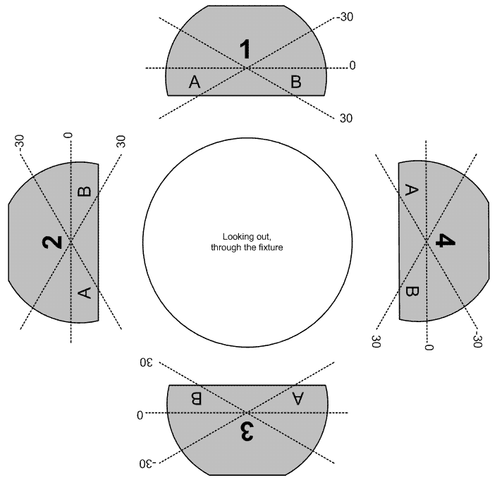
Above: An illustration of the how the frames and their sides are designated.
Frames are indexed from 1 to 4 from the top and clockwise as looking along the fixture onto the projection surface. There are two parallel levels of controls of the frames; individually per frame, as well as all frames together as a package.
On the individual level, frames can be controlled in one of two ways; either by the amount of insertion of the two corners that go into the beam (the depth of corners A and B as illustrated above, for “two-point” shutter systems), or by the amount of insertion (depth) of the centre of the frame and the angle of it (positive and negative angles are illustrated above as -30 and 30 degrees, which are only examples, for “single point” shutter systems). These are simply to different systems that are not interchangeable.
Frame depth levels range from 0 to 2, where 0 means fully out, 1 means at the centre of the beam, and 2 means at the far corner of the beam. So, if frames 2, 3 and 4 are all out and frame 1 has a depth of 1, then the beam is in effect a half moon.
On the group / package level, all frames can be rotated together by a given angle.
| Commands | Description |
|---|---|
SetFramingShutterDepth |
Sets the depth of a frame from 0 to 2. |
SetFramingShutterAngle |
Sets the angle of a frame in degrees. |
SetFramingShutterADepth |
Sets the depth of the A corner of a frame from 0 to 2. |
SetFramingShutterBDepth |
Sets the depth of the B corner of a frame from 0 to 2. |
SetFramingShutterPackageAngle |
Sets the angle of the frames package in degrees. |
CustomFramingShuttersCommand |
Indicates an undefined action. |
7.5.1.11 Wheels
Many fixtures have some sort of multislotted rotating mechanism embedded for picking colours, patterns and effects. We call them all wheels and the slots / contents of them frames.
A wheel as such has the following modes: Indexed, Mixed, Continuous, Oscillating, Spinning and Random. In the first four modes, the wheel can be positioned in terms of which frame is visible where position 1 corresponds to the first frame (often open) and x corresponds to the x’th frame. Sometimes when a wheel has n frames, a position lower than 1 or greater than n is used when a wheel can be continuously positioned all the way back to the first frame. The Mixed mode is often used for fixtures that have DMX snaps or ranges for half-positions, which means the position is then often a .5 values, such as 1.5, 2.5 or 3.5.
When a wheel is in Spinning mode, the Direction of a wheel or frame can either Forward or Reverse.
In Random mode the wheel periodically rotates, positioning it at a random frame.
The Speed of a wheel can be set in all modes and is defined as 0 = minimum speed, 1 = maximum speed and -1 = standstill.
Some fixture also have a WheelShutterMode that blacks out the fixture while any wheel rotates to another position (that is, in any mode by Spinning).
| Commands | Description |
|---|---|
SetWheelMode |
Sets the mode of a wheel. |
SetWheelSpinDirection |
Sets the direction of a spinning wheel. |
SetWheelPosition |
Sets the frame position of a non-spinning wheel by frame index. |
SetWheelSpeed |
Sets the rotation speed of a wheel in any mode. |
SetWheelRandomPositionSpeed |
Sets the speed (and thereby frequency) at which a wheel rotates to another random frame position. The speed of the transition, once it happens, is controlled by SetWheelSpeed. |
SetWheelShutterMode |
Enables or disables the shutter black out on rotation. |
Some fixtures are equipped with animation wheels. We treat these as wheels with one gobo. These wheels normally have the ability to be both taken in and out of the beam, which is referred to as the Depth of the wheel. A depth level of 0 corresponds to fully taken out and a depth level of 1 corresponds to fully inserted.
Often an animation wheel can also be positioned so that the rotation of it appears to be horizontal or vertical, which we call its Orientation. An orientation level of 0 corresponds to horizontal left->right animation, a level of 90 corresponds to vertical up->down animation, a level of 180 corresponds to horizontal right->left animation and a level of 270 corresponds to vertical down->up animation, assuming a Forward spinning direction.
| Commands | Description |
|---|---|
SetWheelDepthPosition |
Sets the level of insertion of a wheel. |
SetWheelDepthStrobe |
Makes a wheel constantly oscillate between fully inserted and fully retracted. |
SetWheelDepthOrientation |
Sets the rotation orientation of a wheel in degrees. |
A wheel’s frame has only the following modes: Indexed and Spinning.
| Commands | Description |
|---|---|
SetWheelFrameMode |
Sets the mode of the frame. |
SetWheelFrameSpinDirection |
Sets the direction of a spinning frame. |
SetWheelFramePosition |
Sets the position of a non-spinning frame. |
SetWheelFrameSpeed |
Sets the rotation speed of a frame in any mode. |
CustomWheelCommand |
Indicates an undefined action. |
The frame of a wheel may contain a prism. Some fixtures have the ability to insert individual prisms not mounted on wheels into the light train. These cases are modelled using wheels, i.e. there may be a wheel with only two frames - one open and one with a prism. Some fixtures also have the ability to move such a wheel back and forth in the light train, creating a scaling effect.
| Commands | Description |
|---|---|
SetPrismScaleLevel |
Sets a level of scaling from 0 to 1 for any prism engaged. 0 means smallest beam output and 1 means largest beam output. |
7.5.1.12 Motion
Includes control of pan, tilt and pitch axis as well as positioning objects along a vector.
Pan and tilt axis can be in one of two modes: Indexed or Spinning. The Indexed mode is the standard positioning mode and the Spinning mode is used for continuous bound-less rotation.
Vector positioning is used for positioning of objects in motion control, including visualisation software virtual cameras and moving scenery. Expect to find either an abstract position range of 0 to 1 or a specific range in meters.
The speed of movement can be controlled both through speed (velocity) and time (to destination). Speed control uses values -1 and from 0 to 1 (where -1 represents standstill, 0 represents slow movement and 1 fast movement) and time control uses values in seconds.
The motion time controls the speed of the motion; the smallest value 0 refers to the least amount of time / highest speed, and the largest value 1 to the largest amount of time / lowest speed.
Each pan, tilt and pitch axis may offer up to two layers of control:
- Individual – The standard and most common layer of control.
- Group – Used in some multi-axis fixtures like the High End Shapeshifter.
The motion shutter mode indicates whether the fixture shutters to black out while an axis is in motion or not.
| Commands | Description |
|---|---|
SetPanMode |
Sets the pan mode. |
SetTiltMode |
Sets the tilt mode. |
| Layered Commands | Description |
|---|---|
Pan |
Pan in indexed mode. |
Tilt |
Tilt in indexed mode. |
Pitch |
Pitch. |
| Commands | Description |
|---|---|
SetPanDirection |
Sets the pan direction in spinning mode. |
SetTiltDirection |
Sets the tilt direction in spinning mode. |
SetPanSpeed |
Sets the pan speed. |
SetTiltSpeed |
Sets the tilt speed. |
SetVectorPosition |
Sets the position along a vector. |
SetMotionSpeed |
Sets the pan, tilt and pitch speed. |
SetMotionTime |
Sets the pan, tilt and pitch time. |
SetMotionShutterMode |
Enables or disables blacking out during movement. |
CustomMotionCommand |
Indicates an undefined action. |
7.5.1.13 Lamp strike / power
Lamp control for fixtures equipped with such.
There are two lamp modes; Normal and LowPower.
| Commands | Description |
|---|---|
SetLampOn |
Turns the lamp on. |
SetLampOff |
Turns the lamp off. |
SetLampMode |
Sets the lamp mode. |
CustomLampCommand |
Indicates an undefined action. |
7.5.1.14 Laser
Some fixtures are equipped with laser aiming devices to assist while focusing them.
| Commands | Description |
|---|---|
SetLaserOn |
Turns the laser on. |
SetLaserOff |
Turns the laser off. |
SetLaserStrobe |
Makes the laser alternate between on and off. |
7.5.1.15 Cooling fans
Some fixture are equipped with a cooling fan that can be adjusted over DMX.
Fan modes are Fast and Slow.
| Commands | Description |
|---|---|
SetFanMode |
Sets the fan mode. |
CustomFanCommand |
Indicates an undefined action. |
7.5.1.16 Effects
For behaviours of dynamic nature, typically some sort of preprogramed motion or colour/effect pattern and even more complex effect engines in multi-pixel fixtures.
In fixtures with multiple effect engines, the GroupName attribute of the Channel element provides the logical link between channels of the same effect engine.
| Commands | Description |
|---|---|
SelectMacroCatalog |
Indicates a numbered and optionally named catalog of macros. |
SelectMacro |
Indicates a numbered and optionally named effect. The number 0 is reserved and indicates disabling any running macro. |
MacroParameterCommand |
Indicates a parameter that is specific to a particular macro. |
Macro |
Indicates a named effect. |
Some effect engines provide dimming and colour control.
| Commands | Description |
|---|---|
SetMacroIntensityLevel |
Macro dimming |
SetMacroColorRedLevel |
Macro red colour mixing. |
SetMacroColorGreenLevel |
Macro green colour mixing. |
SetMacroColorBlueLevel |
Macro blue colour mixing. |
SetMacroColorWhiteLevel |
Macro white colour mixing. |
Some effect engines provide shutter / strobe control.
| Commands | Description |
|---|---|
SetMacroShutterOpen |
Shutter open / full output. |
SetMacroShutterClosed |
Shutter closed / no output. |
SetMacroShutterStrobe |
Shutter strobing. |
SetMacroShutterSpeed |
The speed of shutter strobing, from 0 to 1. |
Some effect engines provide a speed and direction control.
| Commands | Description |
|---|---|
SetMacroSpeed |
The speed of the effect, from 0 to 1, or -1 to indicate pause / standstill. |
SetMacroDirection |
The direction of the effect. |
Some effect engines allow rotating the visual output.
| Commands | Description |
|---|---|
SetMacroRotationPosition |
A fixed angle of the effect. |
SetMacroRotationSpin |
Continuous rotation of the effect, with speed thereof from 0 to 1, or -1 to indicate pause / standstill. |
SetMacroRotationDirection |
The direction of the continuous rotation. |
Some effect engines provide crossfade times when switching macros.
| Commands | Description |
|---|---|
SetMacroFadeTime |
The time it takes to fade between macros, from 0 to 1, or -1 to indicate instant switching. |
When no other commands catches the behaviour, a custom commands also exists.
| Commands | Description |
|---|---|
CustomMacroCommand |
Generic macro control. |
7.5.1.17 Specials
For anything that doesn’t fall into the above categories, the following additional commands are present in the channel layouts.
| Commands | Description |
|---|---|
NoFunction |
Indicates a DMX range with no function that provides an ability to turn off other functions on the same channel. |
Reserved |
Indicates a DMX range with no function, often a DMX range labelled by the manufacturer as “reserved for future use”. |
Custom |
Indicates an action for which a well defined command does not yet exist. We continuously monitor these in order to create new well defined commands. |
Reset |
Resets various components of the fixture. |
7.5.2 Functions
Functions are listed separately following the channel layout. The describe special functionality in the fixture that can only be triggered by special channel level combinations over time.
<Function Type="ResetComplete">
    <Step Time="4">
        <Parameter ChannelIndex="1" DMX="255" />
        <Parameter ChannelIndex="12" DMX="255" />
    </Step>
    <Step Time="0">
        <Parameter ChannelIndex="12" DMX="0" />
    </Step>
</Function>
Above: A function example.
The function example above illustrates how to perform a complete reset of a fixture by bringing both channels 1 and 12 to level 255, holding for 4 seconds and finally bringing channel 12 to level 0.
If the Type attribute is Custom, two additional attributes CustomGroupName and CustomName are also present and used to describe the function. The custom group name is used to group custom functions, but may be empty if no relevant grouping exists.
Please refer to the CEF XML schema for a full list of all function types.